Collision Avoidance Robot
 |


PRINCIPLE:Ø The robot starts moving automatically each time
when the reset switch is pressed, the robot itself finds an obstacle free path
using the IR SENSORSØ Whenever an obstacle appears, the robot changes its
direction towards next near obstacle
free path thus it is said to be collision avoidance robot
- Actuators
/ output devices: 2 geared motors
- CPU:
AMICUS 18
- Power
source: 4-6 AA batteries
- Programming
language: bascom
- Sensors / input devices: IR sensor
- Target
environment: indoor

Materials needed
1 AMICUS 18 Project Board
The Amicus18 hardware is based upon the
world famous Arduino board; however, the Amicus18 board uses a Microchip PIC
micro microcontroller instead of an Atmel AVR type.
It has exactly the same dimensions as the
Arduino, and all Arduino shields will physically fit on the Amicus18 board.
The microcontroller used on the Amicus18
is the Microchip PIC18F25K20, which has 32768 bytes of flash memory, 1536 bytes
of RAM, and operates at 64MHz, which equates to 16 MIPS (Million Instructions per
Second).There are nine 10-bit ADC (Analogue to Digital Converter) inputs, and
two 10-bit PWM (Pulse Width Modulation) outputs, as well as two comparators, a
USART (Universal Synchronous Asynchronous Receiver Transmitter), SPI (Serial
Peripheral Interface), I2C (Inter-Integrated Circuit), and four timers, each with various internal operations attached to them.

Each of the microcontroller’s I/O lines
are brought out for use with external devices such as LEDs, Servos, Potentiometers,
and LCDs etc…
Communication with the Amicus18 board is
through a USB interface, which presents itself as a standard serial port on the
PC. The microcontroller can be programmed directly through this port so there
is no need for a dedicated device programmer, however, if the need arises,
there is an ICSP (In Circuit Serial Programming) interface suitable for all
programmers, but tailored for the Microchip PICkit2tm programmer.
Power can be supplied to the board either
via the USB port, or an external 9 Volt DC source. When powered from the USB
port, a maximum of 500mA (milliAmp) may be drawn, and the USB port is protected
by a resetable fuse. When powered via a 9V source, a maximum of 800mA may be
drawn.
The microcontroller is a 3.3 Volts type,
however, there is also a 5 Volt supply always available.
The Amicus18 board is extremely easy to
use, in fact, no previous microcontroller experience is required..
5 IR SENSOR version-2 with cable
The one
"eye" sends infra red light. The other sees the reflection of this
(if there is one), and the unit returns the distance to the object in front of
it. It has 3 wires (make sure you get the cable for it, or it can be a little
hard to hook up). You give it power on 2 of the wires, and the
third one plugs into the microcontroller, and tells it the distance.5 IR
sensors are required to build the both obstacle avoidance robot and line
following robot.

Robot chaises

It is the robotic base which is required to place
all the objects (boards and sensors) and fit the motors and wheels..
Passive wheels and screws to fit
This wheel is used to move the robot freely in all
directions

2 Geared motors and wheels to fit
It is
very important that your
motors have gears. You want a slow robot; Go for high ratios, like
120:1 or higher, as a slow robot is so much more fun in the beginning, because
you can see what it is doing.
Apart
from that, there is not much to say. Well, that would be, that there are many
ways of moving and steering. This way of only using 2 wheels, is sometimes
referred to as "skid steering". And it is worth remarking that if you'd like to add belt tracks later
on, the basics are the same .

H-BRIDGE
motor driver (L293D)
This board acts as interface between
microcontroller and motors,the motors are connected to this board which is connected to the microcontroller

This
little motor-driver-in-a-chip can drive a pair of small motors (600 mA each,
for the tech interested), without frying the microcontroller. And furthermore;
It can make the motors go backwards. Which is handy when facing a wall :)
Your nice
board can be connected to the motor driver (using the female pins) that can
take a pair of small motors, and make them drive both forward and reverse.
The board
is set up, so the microcontroller's outputs RB4, RB5, RB6, and RB7 are fed into
the motor controller, and out comes 2 fine pairs of wires that you can hook up
to a pair of motors: Motor A and Motor B. And you just soldered pins into them,
how nice.
Batteries
Either 4 AA Non rechargeable, or 6 AA
Rechargeable.
This
robot needs 6-12 Volts. Mainly because the IR, really feels best on 5.0V, that's what
it's made for. Motors and servo would like more, microcontroller could live
with 12.0V, but keeping it simple is the
core here, so we feed the whole robot
with as close to 6.0 - 9.0V as possible. And rather too little than too much,
so we make sure not to fry anything, now that this is your first robot;
Now, you
may know, that normal batteries provide 1.5V. However, you may not know that
rechargeable batteries only provide 1.2V!
No matter
if you knew that or not, 4 times 1.5V from normal batteries, is 6V. and 6 times 1.2V from rechargeables is 7.2V, which
is nice and closer to 12V. And then it is much cheaper in the long run. So I
strongly recommend you to get some rechargeables and a charger.
Tip: The
best rechargeables have the highest capacity, measured in "mAh". The
2500 mAh AA-size is a fine battery.

1 4 x AA Battery Holder if you are using rechargeable batteries
or
1 3 x AA Battery Holder if you are using non-rechargeable batteries
or
1 3 x AA Battery Holder if you are using non-rechargeable batteries
(See more
below, regarding batteries, and why the difference - Point is that you need as
close to 5V as possible, one way or the other, and you can use something
completely different in terns of batteries if you want. As long as it is just
about 5 Volts.)
10-15 Female-Female Header Jumper cables and 4 three pin RMC cables
Yes.
These are nice. When I started this hobby a couple of years ago, these where
really hard to get. Now they are everywhere, and that is really good. Most
things in this new robot-hobby of yours have pins (or you solder some in ;) -
and by using these jumpers, you can make quick connections without soldering.
Nice!


1 Heat shrink tube (5 mm approx)
Sometimes
you do need to solder 2 wires together. For instance the Sharp IR Range finder;
It comes with straight up wires on the plug. What you do, is cut one of the
female cables (above) in 2 parts, solder them together.. but before that, you
cut a little piece of this heat shrink tube to
slide
over the place without insulation. Then with a lighter, you can quickly heat up
the tube, and
it
shrinks to fit.
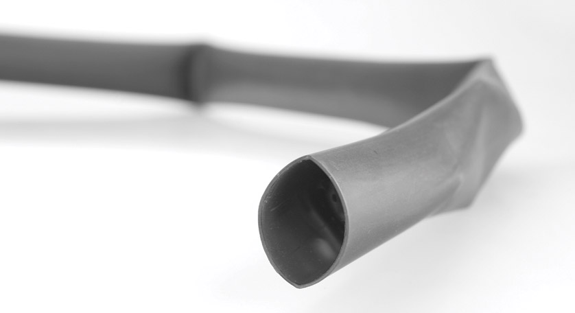
That is
so much smarter than using tape ;)
USB cable
This is
to download the program from the P.C to
the microcontroller
Nice-to-have tools, though not
essential:
A Soldering iron and solder

A computer with an internet connection and a free USB port
Can be
Mac, Linux or PC. The software needed
for this is free.
Ready?
Let's make a robot :)

Fixing up the motors
Mount the
wheels on the geared motors. You may have a completely different set than I do
here, but as long as they are geared motors that run fine on a few volts, and
some nice wheels, you will be all right.
When you
have the wheels on the motors, cut one of the female-to-female wires in halves,
take away some of the plastic from the end of the wire, and solder it on. And
do the same for the other motor.
Make sure
no solder or wires touches the metal on the motor :)
Some
wheels come with optional rubber tyres. It can be a good idea to wait with
putting on this rubber, because if the robot is stuck, it can just slide, which
is nice when testing and developing.
.jpg)
Fixing the motors to the chaises
Fix the
motors to the chaises (after soldering the female pins to the motor) using
screws as shown above, also attach the passive wheel to chaises using the bolts
and nuts.
After
fixing the motors slowly connect the wheels to the motors piston that as
projected out from the chaises using the screws
.jpg)
Building the common 5volt and ground pins
On a bread board fix male berg sticks parallely,
each side having 6-8 pins, solder the berg sticks in such a way that a common 5volts is
obtained from one side and a common ground is obtained from the other side, so
that by giving a 5volt to a pin on one side makes all the pins5 volts that are
shorted to it .similarly the ground is obtained on each pin on the other side.
Mount the bread board on the chaises using bolts
and nuts as shown below…………..
.jpg)
Mounting the amicus 18, IR’s and H- BRIDGE board

Mount the
microcontroller , IR’s and motor driver board on the chaises as shown below
using nuts and bolts.since the chaises is made up of metal short circuits would occur .hence gap
is Maintented between boards and chaises
and also the board will steadily sticked to the chaises .

CONNECTIONS
Connect
the 5v and ground pin of the microcontroller to the bread board, so that many
5volt pins and ground pins are available, which are required by the H-BRIDGE
motor driver and IR sensors.
Connect
the RB4,RB5 pins of PORTB of the micro controller to the IN1,IN2 of the H-BRIDGE
and the pins RB6,RB7
of PORTB to the IN3,IN4.and the pins EN1 and EN2 are
connected to the 5 volts i.e., to the bread board. The pins 12v and gnd pin
in the driver board are connected to the 5volts and ground pins of the bread
board
The pins
motor1 and motor2 of the H-BRIDGE motor driver are connected are connected to
the motors 1 and 2.
Each infrared
sensors will have three pins namely 5v, ground and output (o/p) .give 5 voltage
supply and ground to the IR’s from the bread board and the o/p pins are connected to the i/o ports.. I have been
used the PORTB here, to connect the IR’s i.e, the left IR is connected to the RB3,
the right IR is connected to the RB1, the front IR is connected to the RB2 and
the back IR is connected to the RB0 and these IR’s can be connected to any other pins of PORTA,PORTC
As per your convince.
The Amicus18tm IDE has been designed to maximize programmer productivity by providing highly integrated and intuitive interface to the tools required to develop on the Amicus 18 hardware. The Amicus IDE provides many features for authoring, modifying, compiling, deploying and debugging your programmes. Your program can be compiled while being written, providing instant feedback on syntax errors. This results in an uninterrupted workflow from writing the program code through compiling to downloading the program to the Amicus hardware.
Comprehensive documentation and a helpful and friendly support environment, make using Amicus18 an easy and enjoyable experience for beginners and seasoned programmers.
SOFTWARE
Amicus
is supported by an integrated development environment (AMICUS IDE). The
Amicus18 IDE provides the user with
·
Proton Basic source code editor - with colour syntax
highlighter
·
Compiler - Full version of Proton Basic for
the PIC® Microcontroller with full integration to MPLAB® for
debugging, if required.
·
Programmer - automated programming of the
Amicus Board - no external programmer required.
The Amicus18tm IDE has been designed to maximize programmer productivity by providing highly integrated and intuitive interface to the tools required to develop on the Amicus 18 hardware. The Amicus IDE provides many features for authoring, modifying, compiling, deploying and debugging your programmes. Your program can be compiled while being written, providing instant feedback on syntax errors. This results in an uninterrupted workflow from writing the program code through compiling to downloading the program to the Amicus hardware.
Comprehensive documentation and a helpful and friendly support environment, make using Amicus18 an easy and enjoyable experience for beginners and seasoned programmers.
Programming:
'*********************************************************************
'* Name : collision avoidance robot.BAS *
'* Author : PREM KUMAR.M *
'* Notice : Copyright (c) 2011 All Rights Reserved *
'* Date : 7/27/2011 *
'* Version : 1.0
*
'* Notes :
*
'* :
*
'* : *
'* :
*
'*
*
'* : PORTB.0 = BACK IR *
'* : PORTB.1 = RIGHT IR *
'* : PORTB.2 = FRONT IR *
'* : PORTB.3 = LEFT IR *
'* : 5v = EN1 of
L293D HBRIDGE
*
'* : 5v = EN2 of
L293D HBRIDGE
*
'* : PORTB.4 = In1
of L293D HBRIDGE
*
'* :
PORTB.5 = In2 of L293D
HBRIDGE *
'* : PORTB.6 = In3
of L293D HBRIDGE
*
'* : PORTB.7 = In4
of L293D HBRIDGE
*
'*
*
'*********************************************************************
Device = 18F25K20
Dim wordvar As Byte
Dim floop
As Byte
Dim lloop
As Byte
Dim l_ir
As Byte
Dim f_ir
As Byte
Dim r_ir
As Byte
l_ir = 0
f_ir = 0
r_ir = 0
l_ir = PORTB.3
r_ir = PORTB.1
f_ir = PORTB.2
moto:
High PORTB.4 'RB4 is made 1
High PORTB.6 'RB6 is made 1
Low PORTB.5 'RB5 is made 0
Low PORTB.7 'RB7 is made 0
DelayMS 100
'the above code makes the motors M1 And M2 To rotate in forward
direction '
While PORTB.1 = 1 'when Interrupt
is occured At RB1 '
GoTo right_ir
right_ir:
Low PORTB.4 'RB4 is made 0
High PORTB.6 'RB6 is made 1
Low PORTB.5 'RB5 is made 0
Low PORTB.7 'RB7 is made 0
'the above code makes the motors M1 to halt And M2 To rotate which makes
the body to move in left direction '
Wend
High PORTB.4
High PORTB.6
Low PORTB.5
Low PORTB.7
While PORTB.2 = 1 'when Interrupt
is occured At RB2'
GoTo front_ir
front_ir:
Low PORTB.4 'RB4 is made 0
Low PORTB.6 'RB6 is made 0
High PORTB.5 'RB5 is made 1
High PORTB.7 'RB4 is made 1
DelayMS 500
'delay 500 milliseconds'
Low PORTB.4
Low PORTB.6
High PORTB.5
High PORTB.7
DelayMS 500
Low PORTB.4
Low PORTB.6
High PORTB.5
High PORTB.7
DelayMS 500
'the above code makes the motors M1
And M2 To rotate 3 times in reverse which makes the body to move in
backward direction '
Low PORTB.4 'RB4 is made 0
High PORTB.6 'RB6 is made 1
Low PORTB.5 'RB5 is made 0
Low PORTB.7 'RB7 is made 0
DelayMS 500
'delay 500 milliseconds'
Low PORTB.4
High PORTB.6
Low PORTB.5
Low PORTB.7
DelayMS 500
'the above code makes the motors M1 to halt And M2 To rotate twice which
makes the body to move in left direction '
Wend
High PORTB.4
High PORTB.6
Low PORTB.5
Low PORTB.7
While PORTB.3 = 1 'when Interrupt
is occured At RB3'
GoTo left_ir
left_ir:
High PORTB.4 'RB4 is made 1
Low PORTB.6 'RB6 is made 0
Low PORTB.5 'RB5 is made 0
Low PORTB.7 'RB7 is made 0
'the above code makes the motors M2 to halt And M1 To rotate which makes
the body to move in right direction '
Wend
High PORTB.4
High PORTB.6
Low PORTB.5
Low PORTB.7
While PORTB.0 = 1
GoTo reverse
reverse:
High PORTB.4 'RB4 is made 1
High PORTB.6 'RB6 is made 1
Low PORTB.5 'RB5 is made 0
Low PORTB.7 'RB7 is made 0
DelayMS 100
'the above code
makes the motors M1 And M2 To rotate in forward direction '
Wend
High PORTB.4
High PORTB.6
Low PORTB.5
Low PORTB.7
GoTo moto
regards,
prem
bein in d information tech branch u ve done this kinda robotics projects its superb dude , you are the hard worker dude ...... u stil ve other projects in electronics i think u shud post those on ur blog ..... gr8 wrk dude , keep goin :)
ReplyDelete